Retrobrad has been created and maintained by me - Brad!
This page has been visited times since June 2007

  You should have your SNES console all pulled apart before starting this tutorial. If not then click here to see how to open up your SNES console.  
 

Right then, the first thing you would want to do is drill the two holes for the switches (you can put the switches pretty much wherever you want but i prefer them at the back of the console - it looks better and theres plenty of room there.) If you dont have a drill, i find you can use screwdrivers to do the job (start with a
small screwdriver and 'drill' into the plastic then keep
progressing up with the size of the screwdrivers till you get the right size hole.)

I like to use toggle switches, because they are the easiest to install - they only need a simple round hole rather than slide switches which need a rectangular hole and then two small holes either side to screw the switch in place - but again it all comes down to personal preference.

 
  So now that we have our holes drilled out, we can put the switches in. Once they are in, grab your 2.2K resistor and solder it as shown in the picture (between the two outside terminals).  
  We can set aside our main plastic base for the moment - now we need to work on the mainboard. get your two lengths of wire of approx 15cm each. Solder one of them to the middle post of the Voltage Regulator (which is ground or 0v) then solder the other
wire to the 'O' connection of the Voltage Regulator (which is +5v). You can either solder them to the top side or the underside of the mainboard, i prefer the topside.
 
  This is where your solder wick comes in really handy! if you have a microscope or magnifier, now is the time to use it! lets start with PPU2 - Desolder PIN 30 (which is the labeled leg, right on the end) and lift the leg (but be careful not to break the leg) Then do the same with PPU1 PIN 27 (a little harder to do, just count backwards from the labeled pin 30). You should also be careful not to desolder any of the sorrounding
legs and also not to make solder bridges between them.
 
  Now thats the easy bit out of the way - for this next part you're going to need some good eyesight and steady hands! Locate the two PPU chips that are side-by-side (PPU1 and PPU2) we are going to need to desolder and lift a leg on each of these chips.  
  Now that they are desoldered, get a piece of electrical tape (or masking tape) and place it underneath the lifted pads - as close to the chip as you can. now you can gently push down the lifted pads.  
  Now grab a peice of thin, single strand wire and bend it as shown in the picture so that it connects between the two lifted pads. hold it down initially with a piece of tape, and then solder it to the legs - dont use too much solder!  
 

Once you've done that, grab a piece of wire approx 20cm long and solder it to the bent piece of wire you had just soldered to the two chips. (see picture) this wire will eventually connect to the middle post of one of the switches.

 
  Okay now that part was all about the 50/60hz mod, this next bit is for your lock / unlock switch. locate the little chip right in the corner (see picture) this is where we will solder our wire to. You need to desolder PIN 4 and just as we did previous - lift the leg (without breaking it!) and then stick a piece of tape underneath it. Then get a length of wire approx 20cm long and solder it to the lifted leg (remember - don't use too much solder!) It's a good idea to tape it down once finished to hold it in place (see picture) This wire will go to the middle of the lock / unlock switch.  
 

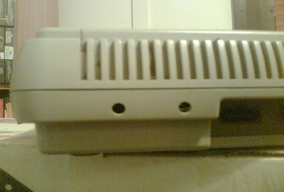
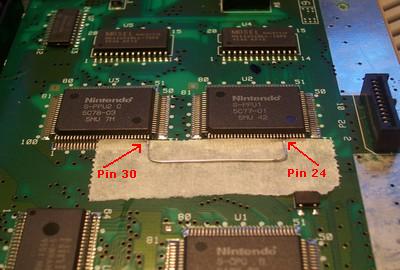
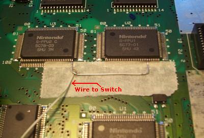
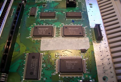
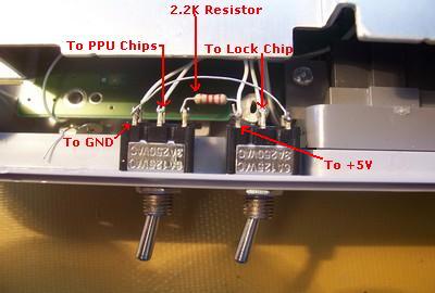
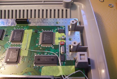
Now that we have all our wires soldered to the mainboard, we need to solder them to our switches. (which is the easy part!) so place your mainboard back into the case and we're set to go. You should have four wires to solder in. (refer to the picture for where to
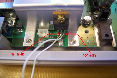
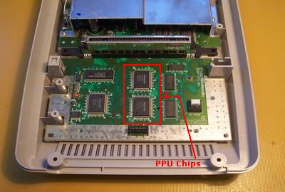
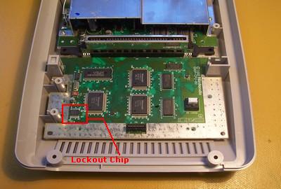
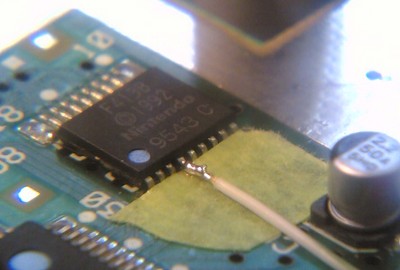
connect the wires) Solder the GND wire to the left switch, left most connector. then get a short length of wire and solder it from that same connector over to the right switch, right most connector. Then solder your wire comming from the two PPU chips to the left switch, middle connector. Next, solder the wire from the lockout chip to the right switch, middle connector, and lastly, solder the +5v wire to the right switch left most connector. and you're done!

The left switch is now your 50 / 60hz switch and the right switch is your lock / unlock switch.

 
  Alrighty then, time for testing! plug your console in and put in a foriegn game to test the lock/unlock switch. In one mode the game should now play and in the other it should! And finally we'll check the 50/60hz mode switch. (you can switch this over while the console is on by the way) turn on your console and in 50hz mode you should notice the screen has black bars on the top and bottom of screen - now flick the switch and the image will expand to full screen! also you will notice the music is now playing faster, and if you play the game, you will notice that the gameplay is faster also!

Alright, you're all done!

 
by retrobrad - 09 June 2007
  Super Nintendo Console  
  Two SPDT switches (single pole double throw)  
  lengths of wire  
  A drill (or someway of drilling holes)  
  Soldering Iron  
  Solder  
  Cutters  
  Electrical Tape (or some other tape)  
  2.2k resistor