Retrobrad has been created and maintained by me - Brad!
This page has been visited
times since June 2007
You should have your Mega Drive console all pulled apart before starting this tutorial. If not then click here to see how to do it.
Work out where you want your switches to go and drill two holes for them. I like to put them at the side of the console but you can basically put them wherever you want. Also, i have used toggle switches but if you prefer you can use slide switches (the principles are still the same but they're a little harder to install).
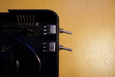
Alright, now that the holes are drilled you can fit your switches - as shown in the photo.
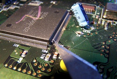
Now that part is out of the way, you will need to locate the big SEGA chip and lift up leg 107 (the leg is easy to find - 105 is written on the mainboard so you just need to count two more legs and you're there!)
To lift the leg you can just get a scalpel and carefully pry it from the pad, I've found that you don't even need to desolder it first, but if you have good eyes or a microscope then i recommend desoldering it then lifting it).
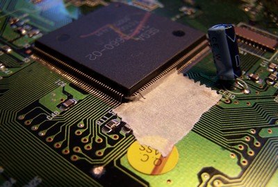
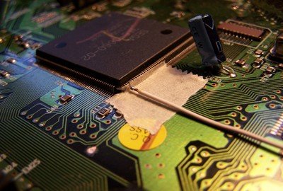
Now carefully solder a length of wire to leg 107 (make sure the wire will be long enough to reach to the switch)
P.S its a good idea to put another piece of tape over the wire once soldered in, to help hold it in place.
Once you have it lifted, place some tape underneath it so it doesn't come into contact with any other legs or pads.
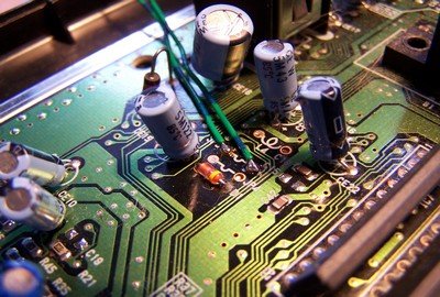
We need to solder a wire to where leg 107 used to be. If you follow the track down from leg 107 you will find a pad - This is the best place to solder the wire to. Since this pad is masked (with that green stuff) you need to scrape the mask off the pad, then solder another length of wire to it (see the photo)
Once you have that part done, put your metal shielding over the mainboard and look for a suitable place to solder a Ground wire to I.E there are loads of little solder bubbles around the outside of the board, solder a length of wire to a bubble that the metal shielding does NOT come into contact with (see the photo to see what i'm talking about).
by retrobrad - 23 June 2007
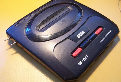
Sega Mega Drive II Console
Two SPDT switches (single pole double throw)
lengths of wire
A drill (or someway of drilling holes)
Soldering Iron
Solder
Cutters
scalpel (or sharp knife)
Electrical Tape (or some sort of tape)
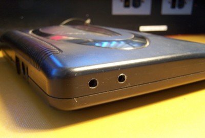
And here it is all closed up and ready for testing!
Here's some screenshots using a Streets of Rage cartridge. Notice the black bars on the top and bottom of the screen in 50hz mode, also when you switch between ENG/JAP modes the games title also changes, you may also find that the music and sound effects and even character names have changed.
And last of all you can see that the 60hz mode gives you a fullscreen image but unfortunately it is not in colour, this requires a more indepth mod that i will cover at a later date.
but for now enjoy your newly modded Megadrive!
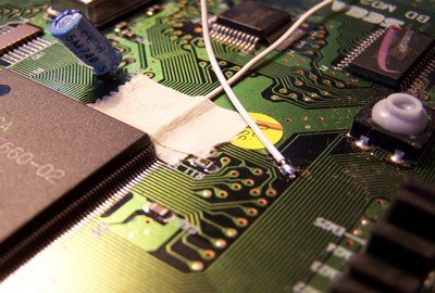
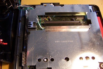
Now that it's all done, you need to route the wires through so it wont interfere with the metal shielding or cartridge slot. (see photo)
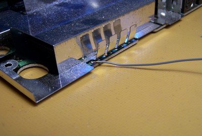
Now get all your wires together and solder them to the two switches. (See the photo for wire locations)
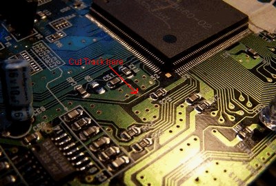
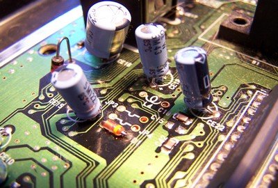
Alright, the last step you need to do on the motherboard is cut a part of the track leading up to JP3. (see the photo for the location of the track to cut)
Solder a wire to each oside of JP3 (make sure these wires will reach to your switches!)
Now that first bit is out of the way you need to locate JP3 - just look for a bunch of capacitors bunched together. This is where we're going to solder our next couple of wires to.